This is the first part of our series on Aluminum Profile Bending & Forming, focusing on the Stretch Bending Process. In this article, we explore how aluminum extrusions are bent using controlled stretching techniques to achieve precise curvature and dimensional accuracy. You’ll learn the principles behind stretch forming, its key advantages, and why it is widely used in industries requiring high-quality, consistent bends in aluminum profiles.
Aluminum alloy extrusions are widely used in bending and forming applications due to their excellent plasticity, lightweight characteristics, corrosion resistance, and high specific strength. In particular, 2xxx, 6xxx, and 7xxx series aluminum extrusions can further enhance their mechanical strength through age-hardening treatments, while maintaining superior surface finishing properties. These advantages make aluminum extrusions especially suitable for manufacturing high-precision stretch-formed curved components.
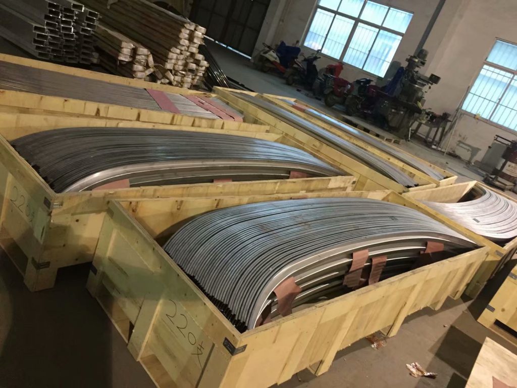
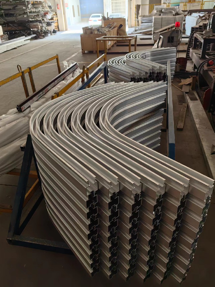
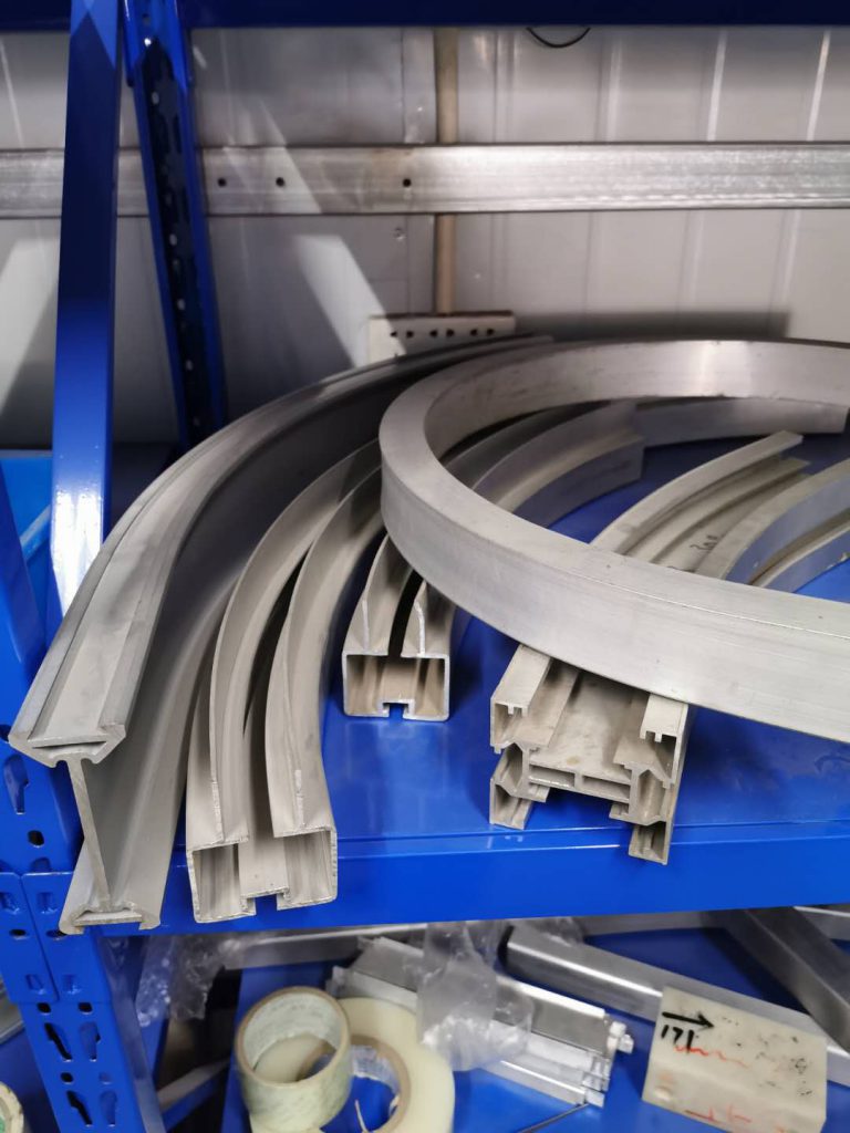
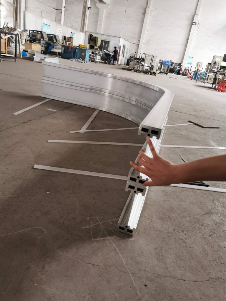
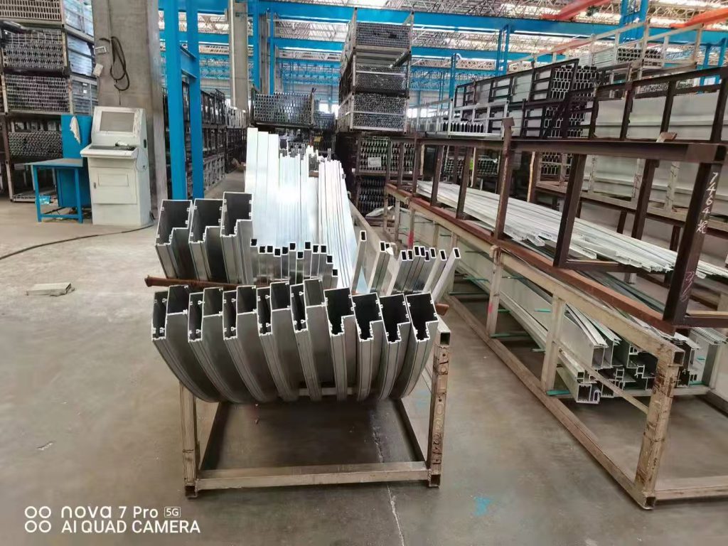
Stretch-formed aluminum extrusion components are extensively applied in rail transit vehicles, aerospace structures, logistics conveyor systems, automotive and ship frameworks, architectural curtain wall systems, medical equipment rails, and high-end interior decoration products. As forming technologies and stretch forming equipment continue to advance, the design requirements for curved extrusion components have become increasingly complex and functional, driving stretch forming processes toward higher accuracy, larger dimensions, and more sophisticated geometric control.
Based on differences in equipment configuration and forming mechanisms, stretch forming aluminum extrusions can be further classified into two-dimensional (2D) stretch forming and three-dimensional (3D) stretch forming. Compared with other aluminum profile bending methods such as roll bending, press bending, and rotary draw bending, stretch forming offers clear advantages in springback control, dimensional consistency, and surface quality, particularly for large-radius and high-precision extruded components.
The following sections provide a systematic overview of stretch forming processes for aluminum extrusions, focusing on equipment structures, forming principles, and typical application scenarios.
Table of Contents
This article series is divided into three sections, each focusing on a different aluminum profile bending and forming method. You may navigate to any process below:
Aluminum Profile Bending & Forming Processes
Stretch Bending Process
https://www.aluminumbendingmachine.com/stretch-bending-forming-process-of-aluminum-profiles;
Roll Bending (Roll Forming) Process
https://www.aluminumbendingmachine.com/aluminum-profile-bending-forming-2-roll-bending;
Press Bending Process
(Coming soon)
Section 1: Stretch Forming Aluminum Extrusions Process
The characteristics of bent aluminum parts typically include a large curvature radius, significant elastic springback, and varying curvature along the longitudinal axis. Because of these unique deformation challenges, aluminum profile bending is widely used in aerospace, aviation, automotive, construction, and high-speed rail industries for forming components such as fuselage frames, wing reinforcements, arched architectural beams, curved window and door frames, train noses, roof contour supports, and structural curved skeletons.
To meet these demanding geometric and dimensional requirements, aluminum alloy extrusion aluminum profiles are extensively shaped using specialized bending techniques. Among various processes, stretch forming has become the most widely used and preferred solution, as it precisely addresses the key forming challenges of aluminum bending—such as large-radius shaping, springback suppression, and profile stability during deformation. By combining tensile loading and bending, stretch forming ensures high contour accuracy, stable cross-section geometry, and consistent surface quality, making it the dominant method for manufacturing high-performance curved aluminum components.
Principle of Stretch Forming
The basic principle of stretch forming aluminum extrusions is as follows: the bending die is rigidly fixed on the machine table, while the clamping and support arms apply controlled tensile force to the extrusion and progressively wrap it around the die. Under the combined action of axial tensile stress and bending moment, the aluminum extrusion enters a plastic deformation state and gradually conforms to the die contour, ultimately forming the required curved component with high dimensional accuracy.
The (2D) stretch forming process mainly consists of three steps.
First, the stretching cylinder clamps the material and applies a pre-stretching force until the profile reaches its yield strength.
Second, the rotary cylinder of the stretch forming machine performs the bending motion, while the stretching cylinder maintains the programmed axial tensile force, guiding the profile to conform to the die surface and achieve the desired shape.
Third, additional tensile force is applied to compensate for the material’s springback, depending on the deformation characteristics of the profile (see Fig. A and Fig. B for the structure of a stretch forming machine).
During stretch bending, the workpiece is bent while the stretching cylinder continuously applies axial tension. The material elongation is simultaneously compensated by the stretching cylinder, preventing wrinkling on the compressed side and ensuring a high-quality curved contour.
Notes: The axial stretch force also mitigates wrinkling on the inner side and optimizes stress distribution, reducing springback and improving stretch forming accuracy.
Characteristics of the Stretch Forming Process
Stretch forming, like roll bending, is a commonly used cold bending method for metal profiles. It features wide applicability and stable forming. It is especially suitable for thin-walled, square tube, and special-shaped Aluminum profiles with a single bending radius.
Advantages
- Capable of forming complex cross-section aluminum extrusions through stretch forming.
- Allows bending of multi-radius and variable-curvature segments.
- Provides high bending accuracy, stable springback control, and excellent part-to-part dimensional consistency.
- Effectively eliminates residual stresses inside the material, resulting in better dimensional stability of the finished product.
- Due to cold work hardening during stretching, the mechanical properties of the material can be improved after stretch forming.
Disadvantages
- Applicable cross-section size is limited by the machine tonnage and clamp dimensions.
- Stretch forming dies require high investment, and their universality is relatively poor.
- For asymmetric profile cross sections, controlling section distortion during stretch forming is more challenging.
Calculation of Forming Force for Stretch Forming Profiles
Calculation of Stretch Force
During technical capability evaluation of a project, three key factors must be considered:
- whether the jaw span of the equipment meets the required tensile length of the profile,
- whether the jaw dimensions match the cross-sectional clamping requirements, and
- the most critical—calculating the maximum tensile force required for stretch forming.
The forming capacity of a stretch-bent part can be estimated as follows:
Ft = 1.25 · Scs · σs
Where:
- Ft — required tensile force of the stretch forming cylinder (N)
- Scs — cross-sectional area of the profile (mm²)
- σs — yield strength of the material (MPa)
A safety factor of 1.25 is applied to the material yield strength to ensure the machine does not operate under maximum load conditions. If the machine’s maximum tensile force is greater than the calculated value, the equipment’s stretching capacity is considered sufficient for the material’s stretch forming requirements.
Notes: To simplify the evaluation process, you can use the online Aluminum Extrusion Stretching Force Calculator below. It allows you to estimate the required tensile forming force based on cross-sectional area and material yield strength, applying the recommended 1.25 safety factor automatically. This tool helps verify whether a specific machine meets the stretching capability needed for your aluminum profile bending project.
👉 Recommended Tool:
Aluminum Profile Stretch Forming Calculator: https://www.aluminumbendingmachine.com/aluminum-profile-stretch-bending-calculator
Calculation of Bending Force and Compensation Stretch Force
In addition to the tensile forming force, stretch forming requires calculating the bending force applied by the rotary cylinder and the additional compensation stretch force applied after bending. Both forces directly influence profile deformation, springback control, and dimensional accuracy.
Bending Force Fb
The bending force required to deform an aluminum extrusion profile depends on its elastic modulus, cross-sectional moment of inertia, and the designed bending radius. The required force can be estimated using:
Fb ≈ (E · I) / (R · h)
Where:
- E — elastic modulus of the material (MPa)
- I — moment of inertia of the profile cross-section (mm⁴)
- R — designed bending radius (mm)
- h — distance from the neutral axis to the outermost fiber (mm)
This force ensures the extrusions reaches the elastic–plastic transition state, enabling continuous die-contact forming.
Compensation Stretch Force Fc
After the bending operation, a supplementary tensile force is required to counteract springback and obtain accurate curvature. This force is intentionally higher than the initial tensile force but must remain below the ultimate tensile limit:
Fc= k · Scs· σy
- k — correction coefficient typically between 1.05–1.15, depending on the curvature and alloy type.
- Fc ensures a controlled additional plastic deformation of 0.5%–1.0%, effectively “locking in” the final geometry.
3D Stretch Forming Machine and Key Forming Technologies
The main frame of a 3D stretch forming machine consists of a welded structure anchored to the foundation, as illustrated in Fig. B. This frame supports the rotating stretching arms and hydraulic cylinders. A worktable is mounted on the top of the frame to hold forming dies. Two stretching-cylinder carriers are positioned on the upper parts of the stretching arms, and their positions are electrically adjusted through motor-driven lead screws to accommodate different workpiece lengths. Each stretching arm is equipped with its own stretching cylinder.
Twisting of the workpiece is achieved by a hydraulic motor with a gearbox located behind the stretching cylinder. The stretching cylinders are mounted on the carriers via universal joints, allowing the clamping jaws to freely rotate forward or backward. A jaw lift cylinder gradually elevates the stretching cylinder during forming, while a jaw pitch cylinder enables upward or downward tilting. The combined movement of all actuators on the carrier (stretching – lifting – pitching – rotating) ensures that the profile undergoes tangential stretching along the die surface throughout the entire forming cycle, thereby producing complex 3D spatial components.
Core Engineering Technologies of 3D Stretch Forming
From a structural and operational perspective, the core technology of 3D stretch forming lies in mold engineering rather than machine actuation. A 3D stretch forming machine does not automatically generate an optimal forming sequence. Therefore, process engineers must perform systematic analysis of material behavior and forming mechanics, supported by CAE-based finite element simulation, and refine both the die and forming program through repeated prototyping until they achieve optimal mold-machine matching and full compliance with part specifications. As a result, this process demands strong engineering development capabilities.
Typical Applications in Transportation Industries
3D spatial components are widely used in high-speed train nose structures and aircraft manufacturing, where lightweight, high-strength, and precision aerodynamic surfaces are required. In addition, the automotive industry increasingly adopts 3D stretch-formed parts for body structural components, roof rails, sunroof frames, impact-absorbing bumper beams, exterior trim with aerodynamic curvature, and EV platform structural reinforcements. These products typically feature demanding technical requirements, substantial mold investment, long development cycles, and high added value.
To meet such multi-axis forming demands—from large aerospace structures to tight-radius automotive profiles—specialized 3D stretch forming equipment such as advanced multi-axis CNC stretch forming machines (e.g., PBF-AS and PBF-AU series Stretch Forming Machines) provides the precision control necessary for reliable complex surface forming.
Key Technologies in Stretch Forming Aluminum Extrusions
The curvature design of stretch-formed parts must not exceed the elongation limit of the material. During Stretch Forming, defects such as wall thinning and fracture, wrinkling, and cross-sectional distortion may occur. These issues are closely related to the mechanical properties of the alloy, the cross-sectional geometry, and the applied Stretch Forming process parameters.
During Stretch Forming, different stress states exist across the deformation zone. Materials outside the neutral layer are subjected to tensile stress, while materials inside the neutral region (in contact with the forming die) experience compressive stress. To prevent wrinkling caused by compressive stress, the applied pre-stretching force must be sufficient to make the material yield in tension. However, higher tensile force intensifies thinning and may cause fracture of the metal outside the neutral layer.
Therefore, determining proper Stretch Forming parameters requires balancing two critical factors: preventing compressive wrinkling in the die-contact region, and avoiding fracture and excessive cross-section deformation caused by overstretching beyond the neutral layer.
In the following section, we may explore Aluminum Profile Roll Bending, discussing how CNC-controlled roll bending machines achieve precise arcs and the challenges of multi-arc parts.
Unlock Advanced Aluminum Profile Bending Technologies!
Our latest article explores the principles of Stretch Bending Forming, highlighting how it eliminates wrinkles, controls springback, and achieves precise 2D/3D curvatures for aerospace, automotive, and architectural applications.
Ready to transform these insights into production power? We highly recommend visiting Stretch Forming Machine. Discover industry-leading CNC stretch forming equipment, explore smart springback calibration solutions, and find custom tooling designs tailored to your high-precision project needs.
👉 Explore Top-Tier Equipment Now: www.stretchformingmachine.com