This calculator is designed for engineers who need precise roll-bending force estimations based on detailed section properties and material parameters.
If you’re not working with structural calculations or simply want an easier way to check bending feasibility, we’ve also prepared a more user-friendly version.
You can try the simplified calculator here:
Aluminum Profile Roll Bending Calculator — Standard Edition
Aluminum Profile Roll Bending Force Calculator — Professional Edition
Calculate theoretical & actual bending forces with safety factor
Profile & Material Parameters
Roller & Process Parameters
Minimum Bending Radius
Used to calculate bending deflection automatically
Theoretical Bending Force:
— N
Actual Bending Force (with friction, roller radius & SF):
— N
Force in kN / t:
—
Safety factor included. Adjust μ, R, SF, or Minimum Bending Radius to see impact on actual bending force.
Profile & Material Parameters
- Elastic Modulus (E, GPa)
- Describes the material’s ability to resist elastic deformation.
- The higher the value, the stiffer the material; more force is required to produce the same deflection when bending.
- In calculations, E determines the material rigidity and is the core parameter in the theoretical bending force formula:
Ptheoretical = 48 × E × I × F/L3
- Deflection (F, cm)
- The maximum vertical displacement of the material along the bending direction during roll bending, also called the bending rise.
- Larger deflection requires greater bending force.
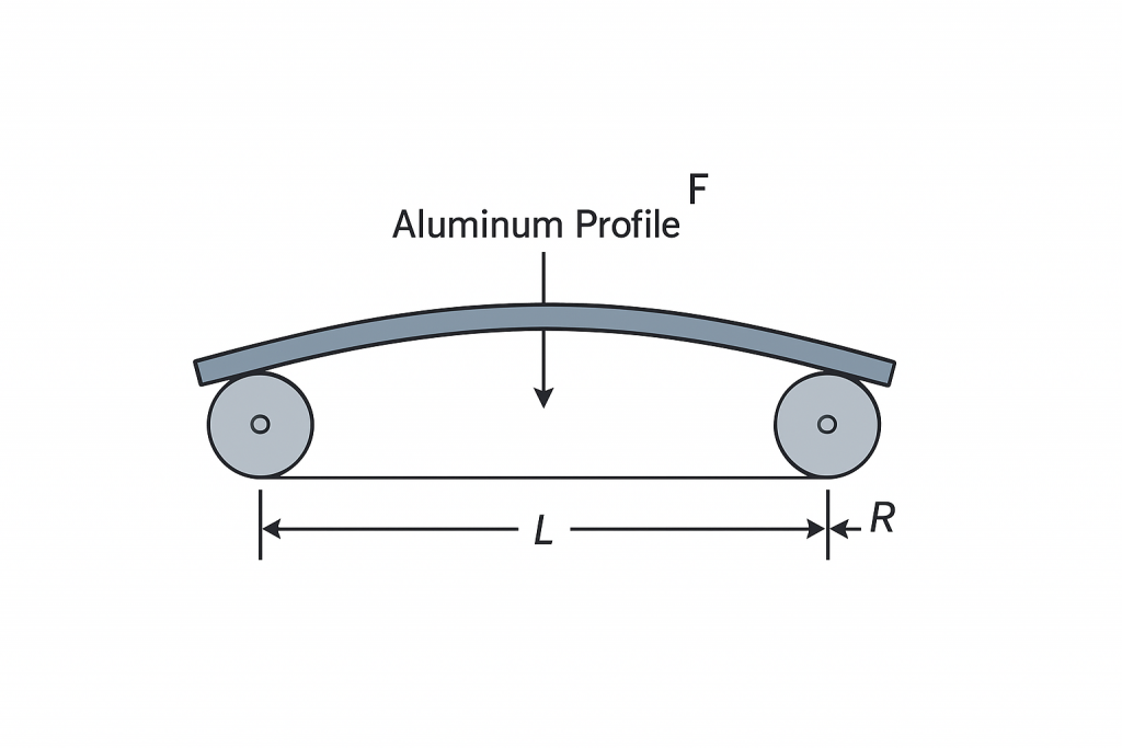
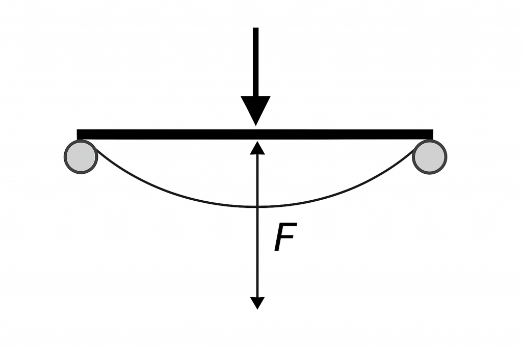
- Imagine supporting both ends of an aluminum profile and pressing down the middle; the deflection is the height the middle sags.
- Deflection (F, cm) refers to the maximum displacement of the material along the bending direction during the roll bending process, that is, the rise of the arc when the material is bent.
- More specifically:
- Imagine supporting an aluminum profile on rollers at both ends, with a force applied in the middle to bend it into an arc.
- The deflection F is the vertical distance from the highest point of the bent arc to the straight line connecting the two ends, measured in centimeters (cm).
- It is a key parameter in calculating roll bending force, because the larger the rise, the greater the bending force required.
- Simple analogy: It’s like placing a ruler supported at both ends and pressing down in the middle—the depth it bends in the center is the deflection F.
- Moment of Inertia (I, cm⁴)
- Describes the cross-section’s resistance to bending and is closely related to its shape.
- The thicker or more distributed the section, the larger the I, and the harder it is to bend the material.
- For a rectangular section, the calculation formula is:
I = b × h3/12}
where b is the width and h is the height. - In the calculator, I is used to compute the theoretical bending force and directly affects the required force.
- Roller Span (L, cm)
- The distance between the support rollers at both ends of the aluminum profile.
- The larger the span, the more the material sags during bending; the required bending force changes with L3.
Roller & Process Parameters
5. Profile Thickness (d, cm)
- The material thickness, directly affecting the calculation of actual roll bending force (considering roller contact and friction).
- Thicker material increases friction and bending resistance, thus increasing the actual required force.
- Roller Radius (R, cm)
- The radius of the roller’s curve.
- Smaller roller radius concentrates stress during bending, increasing the actual bending force.
- The calculator considers R for correcting actual bending force.
- Friction Coefficient (μ)
- The friction between the aluminum profile and the rollers.
- Higher friction requires more actual bending force.
- Safety Factor (SF)
- Accounts for uncertainties in material, process, and measurement, amplifying the theoretical force.
- SF = 1.2 indicates a 20% margin is added on top of the theoretical calculation as a safety allowance.
Relationship of Force Calculation in the Calculator
- Theoretical Bending Force (Ptheoretical)
- Calculated based on material elastic modulus, moment of inertia, deflection, and span, without considering friction or roller radius:
Ptheoretical = 48 × E × I × F/L3
- Calculated based on material elastic modulus, moment of inertia, deflection, and span, without considering friction or roller radius:
- Actual Bending Force (Pactual)
- Corrected for friction, roller radius, profile thickness, and safety factor:
Pactual = Ptheoretical × (1 + kμ × μ + kR × d/R) × SF - kμ and kR are empirical coefficients used to adjust for friction and roller radius effects.
- Corrected for friction, roller radius, profile thickness, and safety factor:
- Unit Conversion
- N → kN → t, for engineering applications and actual equipment selection.
Summary
- E, I, F, L determine the theoretical bending force.
- d, R, μ, SF correct for actual production force requirements.
- Moment of Inertia (I) quantifies the cross-section’s resistance to bending and is one of the core parameters for understanding roll bending force calculations.
Reference Table of Elastic Modulus (E) and Yield Strength (σₛ) for Aluminum Alloys in Common Tempers
| Aluminum Alloy | Temper/Condition | Elastic Modulus E (GPa) | Yield Strength σₛ (MPa) | Notes |
|---|---|---|---|---|
| 6061 | T4 | 69 | 145 | Solution-treated + naturally aged |
| 6061 | T5 | 69 | 200 | Solution-treated + artificially aged |
| 6061 | T6 | 69 | 240 | Solution-treated + artificially aged & strengthened |
| 6063 | T4 | 68–70 | 90 | Solution-treated + naturally aged |
| 6063 | T5 | 68–70 | 130 | Solution-treated + artificially aged |
| 6063 | T6 | 68–70 | 170 | Solution-treated + artificially aged & strengthened |
| 6082 | T6 | 69 | 260 | Commonly used structural profiles |
| 7075 | T6 | 71 | 503 | High-strength aerospace-grade aluminum |

I tried the Roll Bending Calculator, and it feels a bit too technical for me. Maybe you could consider making the original calculator more user-friendly.
Yes, it’s too technical. Perhaps you could try the following calculator.